How we achieve it and the benefits
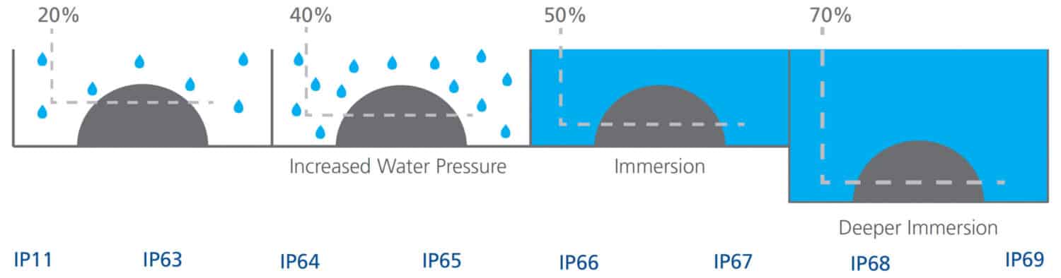
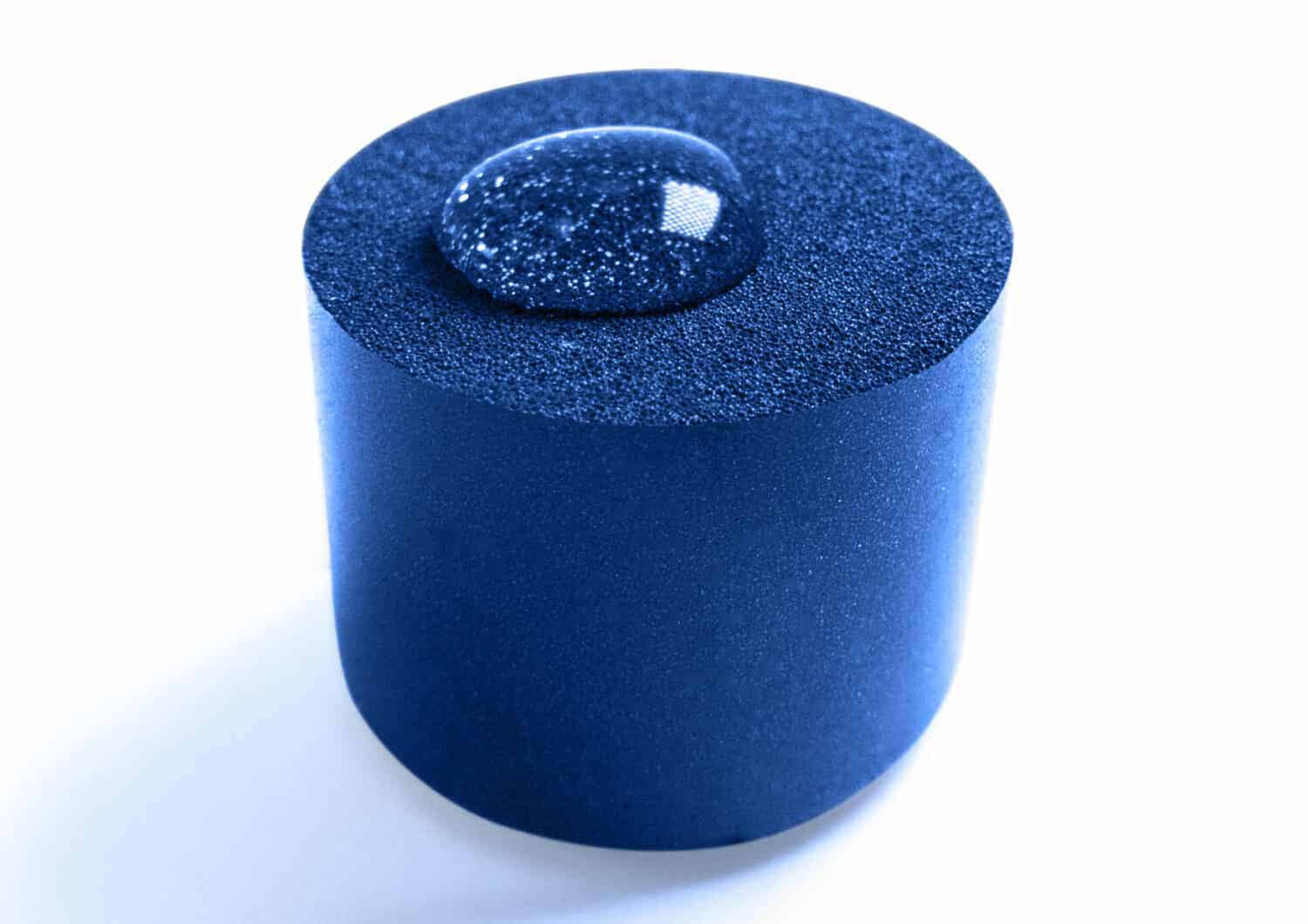
Robafoam’s foam seals have a predominantly closed cell structure. This means that they aren’t reliant on surface skin integrity for it to work and they perform well with watertight Ingress Protection (IP) rated seal requirements. In this blog post we will look at how an IP rating is achieved and the different components which can adapt it to the customer’s requirements.
Our foam characteristics
The 1K foam we create is a unique single part, low temperature heat curing foam and so isn’t reliant on any additional chemicals to be added to apply or cure it. The process takes the raw material from a drum, mechanically mixes it with an adjustable amount of air and then robotically applies to the part. The amount of air used in this process impacts the foam hardness, the more air added the harder the foam will be. Generally, the harder the foam the higher the sealing performance.
The part itself also plays a role in its sealing performance. Its flexibility, span, wall thickness and the size of the fixing points all have an impact on the seal. Although most problems can be overcome by adapting the compression, foam hardness or bead size, it is still crucial for designers to be taking the sealing of a part into consideration early in the designing process.
Achieving an IP rating – The relationship between bead size, hardness and compression
There are three main components to consider when looking to achieve an IP rating:
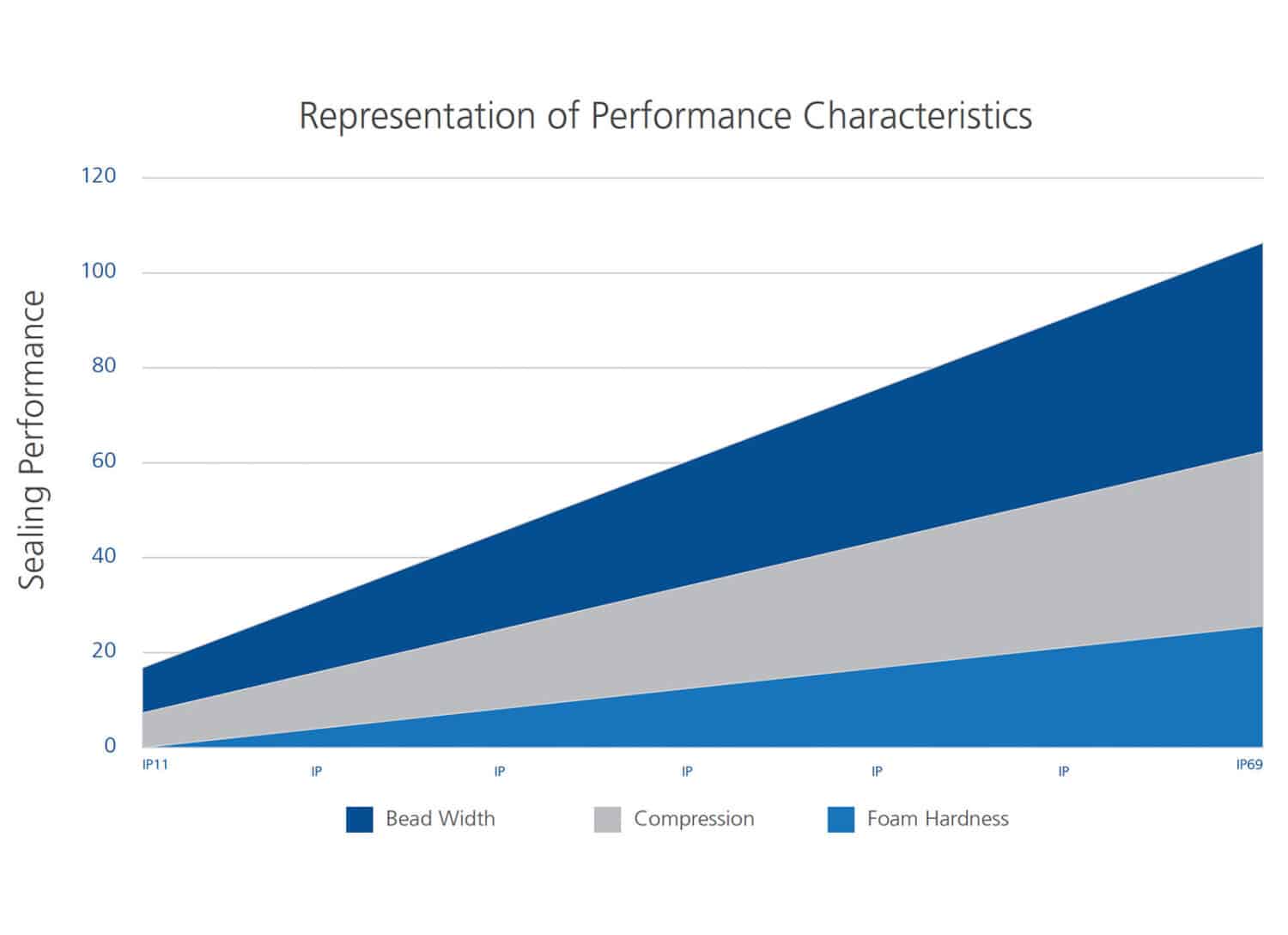
That being said, all elements can be adapted to fit with different requirements or differences in the part. As each individual part has certain seal requirements, the three factors much be varied to work with that part. For example, a part that has a butt joint may need to have the foam bead size increased to achieve a better IP rating, something that is not possible if using a tongue and groove joint. In this case, the bead may need to made higher or harder to improve the IP rating. Below are some more details on how we adapt these three key elements.
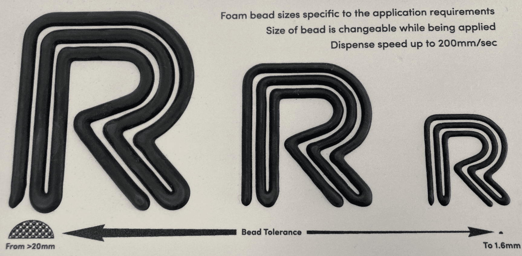
Change in bead size
By adjusting the flow rate, we can increase or decrease the volume of foam being applied. We are also able to produce different foam bead thickness within the same application by programming the robot to change speeds. This means that parts can have varied seal thicknesses without the need to stop and start the process.
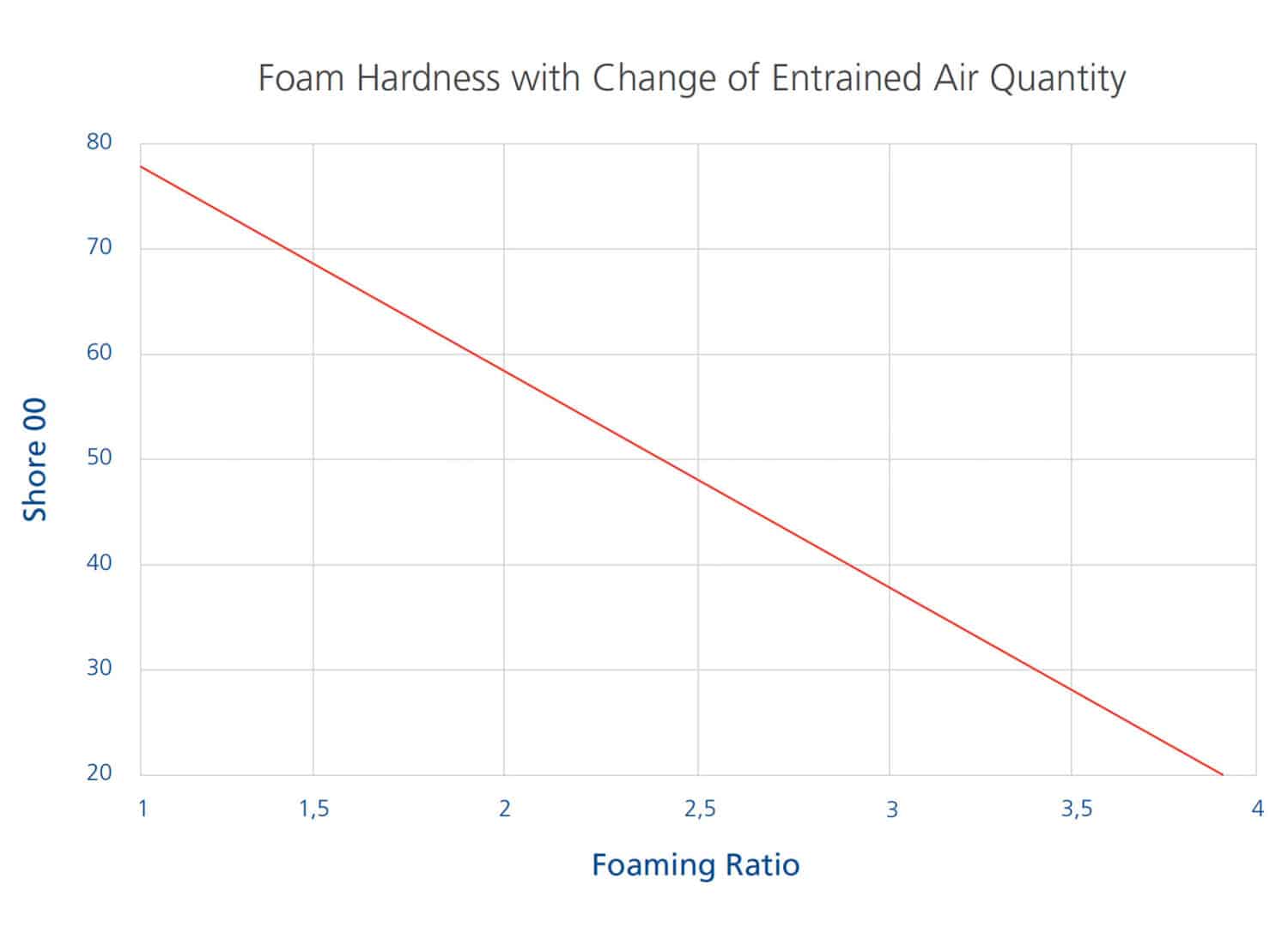
Foam hardness:
By changing the frequency of the pulse valve, in relation to the movement of the piston pump movement (constant flow rate) it is possible to increase or reduce the levels of entrained air. Therefore, change the final hardness of the foamed material applied to the part. So, from the one base material a wide range of hardness’s can be created. We refer to this as a change in Foam Ratio. This foam ratio is the change in weight of a known volume of material. For example ratio 3.0 is 1/3 the weight of the unfoamed raw material.
Compression
As shown in the diagram below, the same bead size can be compressed within a range of different joint types to different percentages, in order to create different IP ratings. By looking at each individual part and its joint design, we can offer advice and recommendations for the best bead size, and joint design adjustments, to work with the compression that is needed. The compression is calculated dimensionally by the change in height. If the part uses a tongue and groove joint design, this is measured from the end of the tongue and therefore is generally the most reliable way of creating a higher IP rating.